Ball mill type, ball mill specifications ball mill model parameters
One, the type of ball mill
(I By length-diameter ratio: length-diameter ratio is the ratio of simplified length and diameter of the mill. The length to diameter ratio below 2 is the short mill, also known as the ball mill, generally for single bin, for rough grinding, multiple ball mills in series can be used as a first-level mill. Medium length mill with length-diameter ratio of 2~3. Length-diameter ratio above 4 is long mill, also known as tube mill, its interior is generally divided into 2~4 bins.
(2) according to the shape of grinding body. The ball mill is filled with a steel ball or steel section. The ball mill is generally a tube mill. The first bin is equipped with cylindrical steel rods. After that, each bin is equipped with steel balls or steel sections, and the rod length should be 1 shorter than that of the rod bin. About 0 mm is appropriate, in order to facilitate the parallel arrangement of steel bars, prevent cross, rod mill is mainly used for wet grinding.
3 according to the discharge mode: according to the discharge mode, it can be divided into overflow discharge, grid discharge, peripheral discharge and simplified central peripheral discharge. The main discharge mode is overflow discharge and grid discharge.
When the ball mill is running, the material is piled up at the left end of the simplified body after feeding into the cylinder. Because of the rotation of the simplified body and the movement of the grinding body, the material gradually spreads to the right end and finally flows out of the hollow shaft at the right end, so it is called the overflow type ball mill.
Another ball mill has a grid near the discharge end. The grid plate is composed of a number of fan plates, fan plate has a width of 8~20mm sieve hole, the material can be gathered in the space between the grid plate and the right end cover through the sieve hole. There are several radial lift plates in this space. When rotating, the lifting plate will lift the material up, the material falls through the conical block and to the discharge end, through the right end of the hollow shaft discharge. Due to the action of grid plate and lifting plate, the material level at the discharging end is low, which accelerates the discharge and increases the production.
(4) According to the transmission mode, the sub-center transmission is that the motor drives the hollow shaft of the unloading end of the mill through the reducer, and the outlet shaft of the simplified rotary reducer and the center line of the mill are coaxes. Edge rotation is that the motor drives the big gear fixed on the unloading end barrel through the reducer to drive the rotation. Other operating processes are dry, wet, coal grinding, with drying bin type, wind sweep type and so on.
Two, the structure of the ball mill
A ball mill
Ball mill is also a single bin mill, by the feeding department, feeding department, bearing department, cylinder department, discharge department, transmission department, deceleration department, motor and other components.
(1) feeding part - ball mill feeding is inclined chute feeding, its elevation Angle is greater than the static friction Angle of the grinding material. The lower half of the inclined chute section is semicircular (no dead Angle), and the square can also be used. There is a sealing device at the connection between feeding garnet and feeding part, and the sealing filler (asbestos rope, graphite filler) is used to seal the connection. Its function is to prevent the material from being poured out due to the accumulation of material in the feed part after feeding. There is also a spiral feeder or a scoop feeder installed in the hollow of the journal of the feeding part, and the material and liquid in the feeding department are dug into the feeding part.
(2) Feeding part - in order to better transport materials, feeding end hollow shaft is equipped with cast copper village set. There is a spiral line cast on the bushing, the spiral line is left or right rotation according to the direction of the mill, but the material must be pushed into the mill barrel through the spiral.
Bearing part - a main bearing before and after the hollow shaft, is supported by a semi-circular sliding bearing, bearing lower part of the semi-circular bearing, bearing lining material for bearing alloy. The upper part of the bearing seat has tubing to spray lubricating oil to the shaft for lubrication and cooling. The bearing base can slide along the axial direction at the feeding end of the ball mill to solve the problem of thermal expansion of the mill barrel caused by the rising temperature during the mill operation. It can avoid the axial temperature expansion stress caused by limiting expansion elongation.
(4) Cylinder body -- the cylinder body is made of ordinary Q235A steel plate. Both ends are connected with large flanges and cast steel grinding caps. The discharging end of the cylinder body is provided with a sieve plate at the connection between the end cover and the cylinder body to prevent the steel ball and steel section from flowing out of the discharging end. The cylinder body is equipped with a certain weight, according to a certain proportion of the diameter of 25-150mm steel ball or steel section as the grinding body. Cylinder body
The lining plate with a certain shape and material can not only prevent wear and tear, but also affect the movement law of the steel ball, thus affecting the grinding efficiency. The lining plate is made of high manganese steel, high chromium cast iron, medium manganese nodular iron and rubber, etc. The thickness of the lining plate is usually 50~130. There are plywood, rubber pad, asbestos rubber pad and so on between the lining plate and the cylinder. The lining plate is generally fixed on the simplified plate with bolts, and there are rubber rings and metal washers below the nut to prevent slurry leakage.
There are manholes on the cylinder body, open the closed manhole cover after stopping, you can go in to replace the lining plate, partition plate, sieve plate or supplement the steel ball steel section. The commonly used lining plate shape is shown in Figure 1-26. The smooth shape of the lining plate makes the relative sliding between the steel ball and the lining plate larger. It produces more grinding effect, and the lifting height of the steel ball at the same speed is more than the work consumed by the projectile, which is suitable for fine grinding. The lining plate with higher convex part has strong pushing effect on the steel ball, so that the steel ball can rise to a higher position and the impact effect is strong. Rubber village board wear resistance (life than manganese steel lining board 2-3 times higher), light weight (than manganese steel village board about 85% lighter), convenient disassembly, low noise.
The discharge part - a hollow shaft discharge end is provided with a inclined truncated conical cast steel bushing, bushing is cast with spiral blades, bushing is provided with a fixed non-rotating screen. The material or slurry flows out of the village through the screen mesh to grind small steel balls and steel sections out of the mill.
⑥ Transmission part - a single bin mill is generally edge drive, now also has a center drive. There is a big tooth ring at the connection between the discharging end and the end cover of the cylinder body. Motor through coupling and reducer and high-speed shaft connection, also useful synchronous motor through gear coupling to drive pinion cylinder big tooth ring. The low speed shaft of the reducer is also connected by the coupling and the pinion. The pinion is driven to rotate the big gear ring and the pinion meshing transmission rotation and the barrel is turned up. The edge drive can be made into right drive and left drive according to the location and installation needs
B pipe mill
Take 4m×13m ball mill as an example. The mill is center drive, center discharge, four bin type, see circles 1-28. Cylinder 7 is driven by jR2-800-8 type motor 23 with a power of 800 kW and hollow shaft 9 at the outlet of the mill
L9.2 r/min. Inside the mill, compartments 9, L and 13 separate the cylinder into four compartments. The first warehouse (from the end of the feed) uses steel rods as grinding bodies, and the other warehouses are loaded with steel balls (the fourth warehouse can also be loaded with steel sections). Wet operation.
Between the first and second storehouse is a transition double storehouse board 9. The surface of the first bin is the blind plate, and the surface of the second bin is the calculating plate. The blind plate and the calculating plate are respectively installed on the base of the compartment plate. The compartment plate is bolted to the plate. The material and water enter the first bin through the feeding device I through the hollow bushing 2. The slurry in the first bin flows through the fixed ring in the center of the blind plate to the two plates and enters the next bin through the calculating plate. Large or broken abrasives are kept between the two plates and removed regularly. Two, three and three, four between the use of single-layer compartment board. Mesh distribution is polygon, divided into outer ring plate and inner ring plate, material is high manganese steel. The corrugated village board 8 made of high manganese steel is installed in the first warehouse, the stepped village board 10 o is installed in the second warehouse, and the small corrugated lining board 12 and 15 made of alloy white iron are inlaid in the third and fourth warehouse. The lining plates of the first and second bins are fixed on the cylinder body by bolts, and a layer of plywood with a thickness of 3 mm is laid between the cylinder body and the lining plate. Waste rubber auxiliary belt can also be padded to prevent the abrasion of materials or grinding bodies from entering between the cylinder body and the lining plate. Small corrugated lining boards and briefs in bin 3 and 4
Cement mortar is poured between the bodies.
In order to improve the grinding efficiency of the mill, the retaining ring 14 and the retaining ring 16 of high manganese steel are installed in the fourth bin, which are fixed on the cylinder body with bolts. The outlet plate 17 is installed at the outlet of the fourth bin, which is composed of the inner and outer ring outlet plate, and is fixed on the outlet end cover of the mill with bolts through the counting plate frame.
The end cover of the mill is welded with thick steel plate and welded into a whole with the cylinder body. The lining plate 6 inside the end cover is connected with bolts. Cement mortar is poured between the end cover and the lining plate. The inlet and outlet hollow shafts of the mill are connected with the end cover of the mill by bolts. A conical sleeve 2 is arranged in the hollow shaft at the feeding end, and a spiral sleeve 18 is arranged in the hollow shaft at the discharging end to protect the hollow shaft from material wear, and the spiral sleeve can push the material out of the mill. Cement mortar is used for the clearance between the bushing and the hollow shaft, and the hollow shaft is installed on two sets of fixed automatic self-aligning bearing 4. In order to ensure good lubrication of the bearing, lubricating devices 24 and 26 are respectively installed near the bearing for circulating lubrication.
Lubrication of main bearing is an important problem. The simplest is oil cup drop lubrication and wool lubrication, and the more perfect is dynamic pressure oil film lubrication of thin oil circulation system, see Figure 1-29). The oil from the pump in the system flows into the upper part of the journal through the small oil pool and overflow baffle on the upper part of the bearing, and is brought into the oil wedge by the oil ring on the upper part of the journal. The lubricating oil thickens between the journal and the bushing
The degree of about 0.05-0.08 mm oil film. The dotted line in the figure shows the dynamic pressure distribution curve when the mill is running. When the load is too large, the gap between the journal and the bearing bush is not appropriate or the viscosity of the oil is not appropriate, the oil film can not be formed, then dry friction occurs.
Sometimes before the mill starts, a manual high pressure pump is used to fill the bearing with oil through the high pressure oil pump, and the high pressure oil forms an oil film between the journal and the bearing bush to float the journal. By starting the mill at this time, dry friction can be avoided and friction can be reduced during starting. Another perfect lubrication method is hydrostatic oil lubrication, the use of high pressure oil pump pressure of about 7 MPa into the high pressure oil inlet of the bearing bush, forcing the journal and the bearing bush to separate, and forming a thickness of about 0.2mm oil film. Even if the journal stops rotating, this oil film still exists, so it is called hydrostatic oil film lubrication. The material from the feeding device into the mill, after grinding in each warehouse, through the transmission pipe (also known as discharge pipe)2I to the cylinder sieve of the discharge device 20O, through the sieve precipitate grinding.
Three, ball mill specifications and technical parameters
Technical parameters of energy-saving ball mill
Simplified speed
Put the ball quantity
The feeding granularity
The discharging granularity
The motor power
model
Output (t/h)
Heavy machine (T)
r/min)
( t )
mm )
mm)
kw )
900 x 1600
1.5
< 20
B. oT5-0.89
65-2
16.5
3.6
800 x 3000
2.7
K20
B. oT5-0.09
1.1-3.5
22
4.6
1200 x 2400
2
3.6
25 or less
. 0 0-0.6
1. 5-4.8
45
12.5
1200 x 3000
32
5
425
P. 074-0.4
1.6 5
45
12.8
1200 x 4500
2
7
25 words
D. 0 t4-0.4
1.6.5.8
55
13.8
1500 x 3000
27
B
The < 25
D. 074-0.4
2-5
a0
17
1500 x 4500
27
14
25 or less
P.O T4-0.4
G-6
110
21
1500 x 5700
27
15
Area 25
B. or4-0.4
6.5-8 -
132
24.7
1830 x 3000
24
11
25 or less
P. 0 t4-0.4
4-10
180
28
1830 x 6400
24
23
25 or less
B. Or4-0.4
6.5-15
210
34
1830 x7000
25
25 or less
B.o. 74-0.4
7.5-17
245
36
2200 x 55 o0

Betty 86 158 5636 2791
Star 86 18756355533 starwang577322@foxmail.com
Address: Heli Industrial Zone, Ningguo City, Xuancheng, Anhui Province, China.
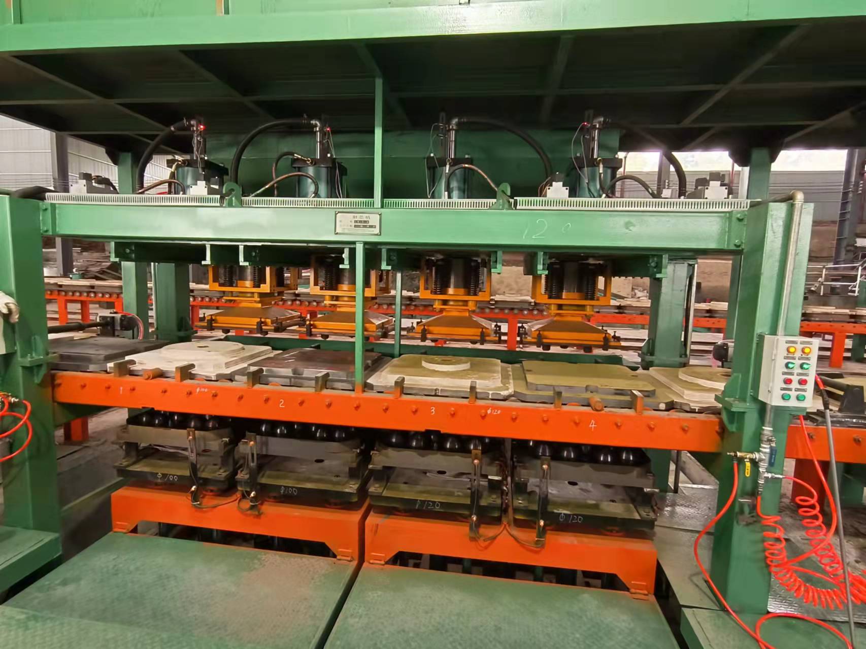
molding line
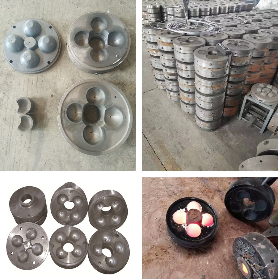
metal mold
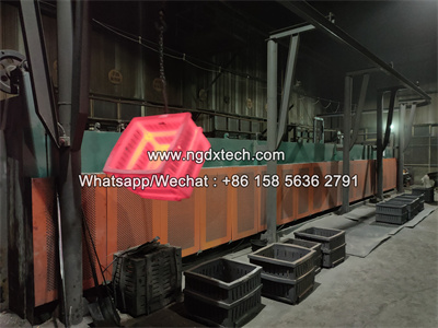
heat treatment furnace
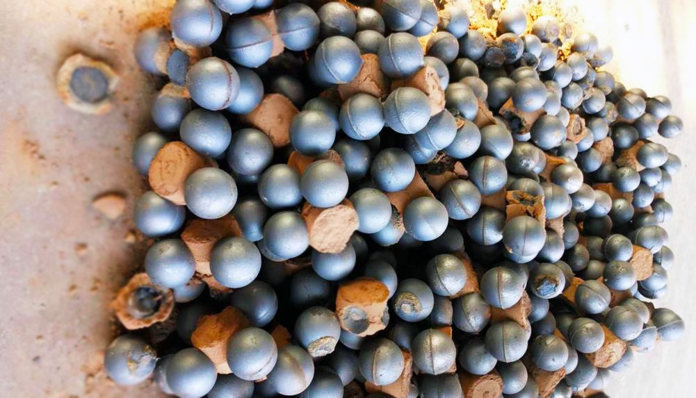
grinding media
Ball Production Ancillary Facility
Wrench

Ningguo Dexin New Material Co., Ltd. all rights reserved